Burguburu et al. (2011): Flame stability for KERO spray with H2 addition
Title
Effects of H2 Enrichment on Flame Stability and Pollutant Emissions for a Kerosene/Air Swirled Flame with an Aeronautical Fuel Injector
Authors
Joseph Burguburu, Gilles Cabot, Bruno Renou, Abdelkrim M. Boukhalfa, Michel Cazalens
Summary
Flame stability is strongly affected by hydrogen injection and the lean blow off (LBO) limit can be reduced. A small amount of H2 is sufficient to reduce CO emissions by a factor of 4 due to the enhancement of reactions involving hydroxyl radicals. NOx emission rises with the increase in H2 concentration, even though the adiabatic temperature remains constant.
- Experimental conditions:
- Pressure: 0.3 MPa
- Preheated air temperature: 500 K
- Primary and secondary air flow rates: 54, 27 g/s
- The airblast injector generates a spray SMD close to 50 \(\mu m\).
- Swirl number: 0.73 (leads to an IRZ)
- Two different hydrogen introductions:
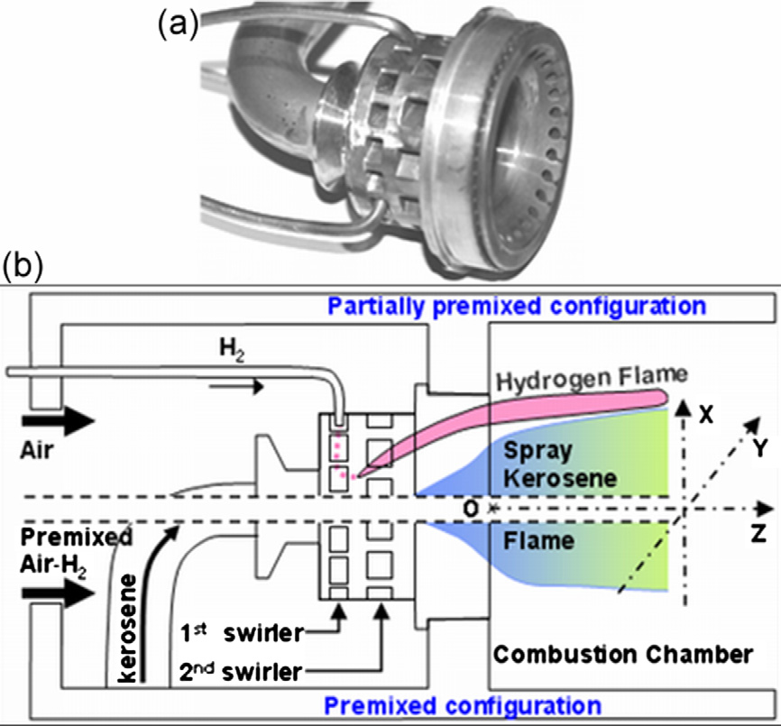
Non-reacting burner characterization
The velocity measurements were performed at atmospheric pressure and for a fixed temperature of 300 K, without fuel injection and dilution air. (See Fig. 2)
- The intense swirl motion generated by the injection system creates an internal recirculation zone (IRZ). For a swirl number greater than the critical value of 0.6, strong radial and axial pressure gradients are set up near the nozzle exit, resulting in axial recirculation in the form of a central toroidal recirculation zone.
- A corner recirculation zone (CRZ) appears due to the flow’s sudden widening at the outlet of the injection system.
- A local counter-current flow is formed and located between the CRZ and IRZ. Most of the time, the reactio takes place close to this intense shear layer.
Flame stability and lean blow off
Hydrogen enrichment has a positive effect in the widening of the flame stability domain. The difference between two configuration, i.e. PP and FP, can be explained by the analysis of the flame structure.
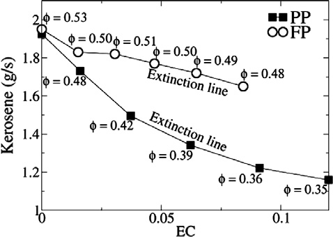
<Stability diagran and LBO limit for various EC>
- PP: Hydrogen/air pilot flames are located in the injection system center core and are stabilized at the first swirler exit. This is due to the high burning velocity of H2/air flames. These flames powerfully preheat the air from the second swirler. This improves the fuel droplets’ evaporation rate and helps preheat and homogenize the mixture.
- FP: The pilot flames are absent from the FP configuration. As the H2 and primary air mixing occurs far upstream, the local H2 equivalnce ratio is too lean to generate a pilot flame into the swirler.
- Pollutant emissions
- The hydrogen injection dramatically increases the NOx meissions. (See Fig. 6a)
- The impact of H2 enrichment in the FP configuration is much smaller than the PP configuration.
- Increasing EC (H2 enrichment) leads to a strong decrease in CO emissions: Two factors
- The replacement of a carbon-containing fuel by a carbon-free fuel: This contribution is known to be very low.
- The changes in the chemical kinetics brought on by the hydrogen addition: The oxidation mechanism for CO depends on the presence of hydrogen containing compounds.
- H2 molecules are oxidized into H2O.
- Small quantities of H2 or H2O increase tremendously the oxidation rate of CO.